How to model an avalanche path

If you google “how to model an avalanche”, you’re likely to turn up almost entirely results about computer modeling of avalanches. Not helpful! I went into this one mostly on my own.

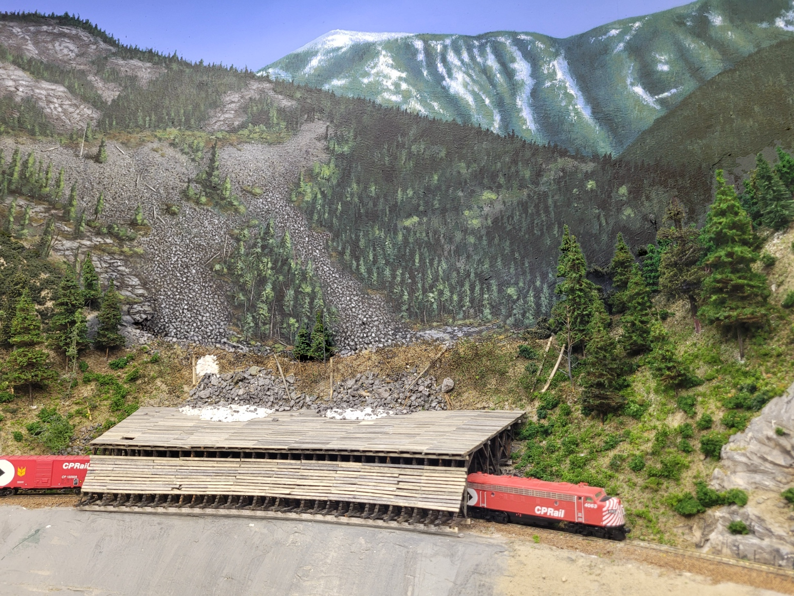
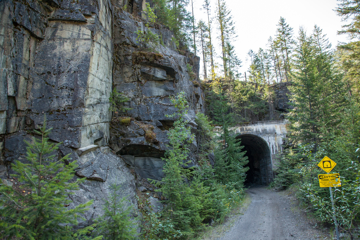
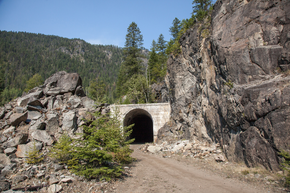
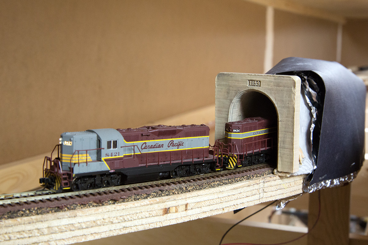
In the end I’ll have 2 avalanche paths on the KD – The McRae canyon/Paulson Gap slops with snowshed, and one at mile 93.6 of the Nelson sub along Kootenay Lake with a slide fence and perhaps signals. The latter is a long way off, but I’ve finished (I think) the former.

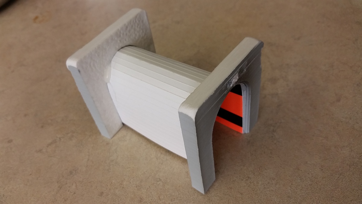
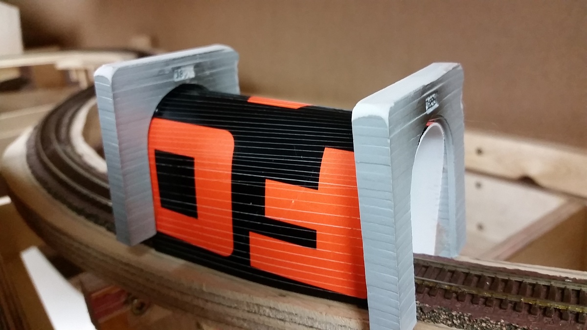
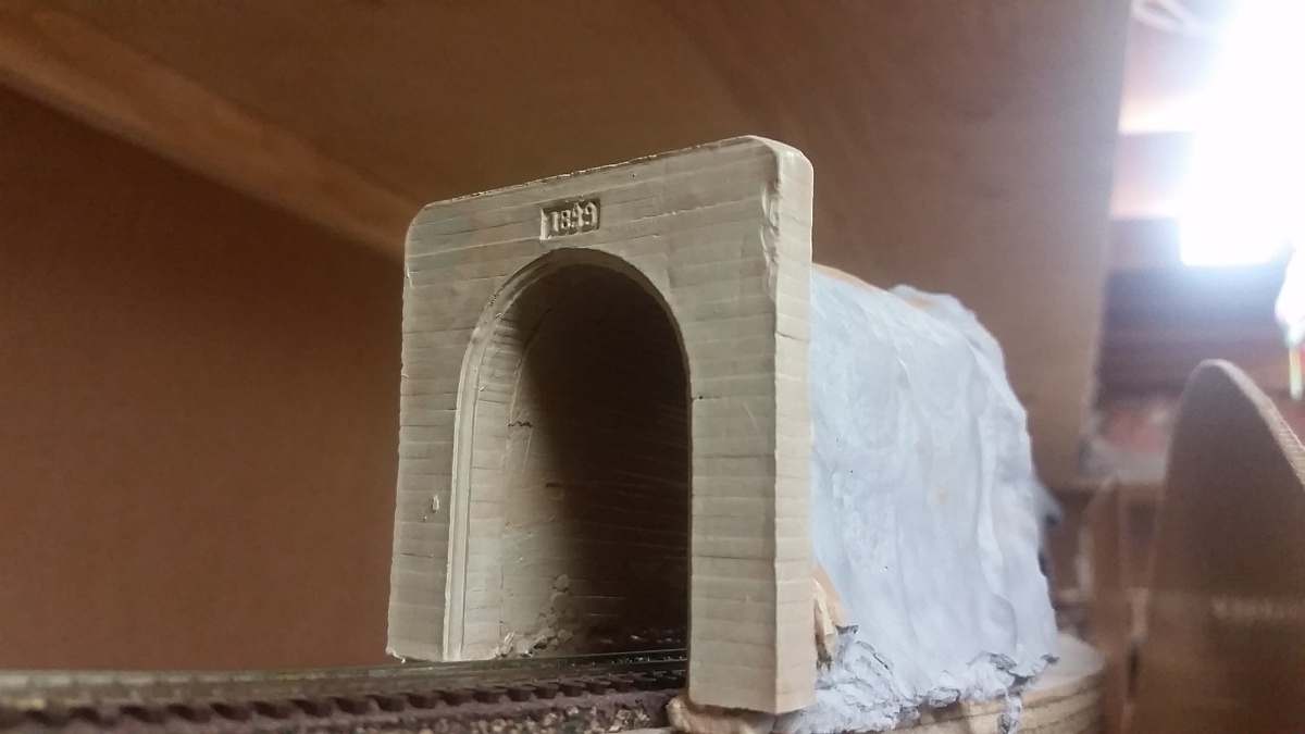
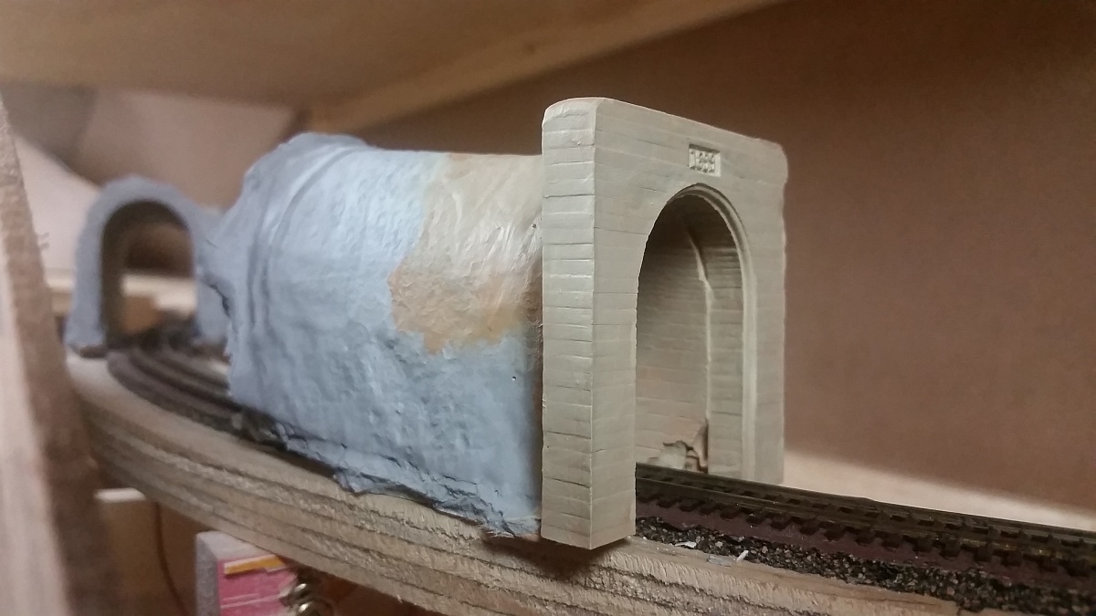
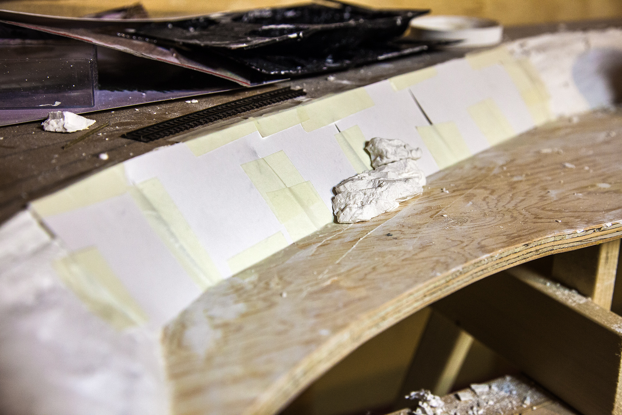
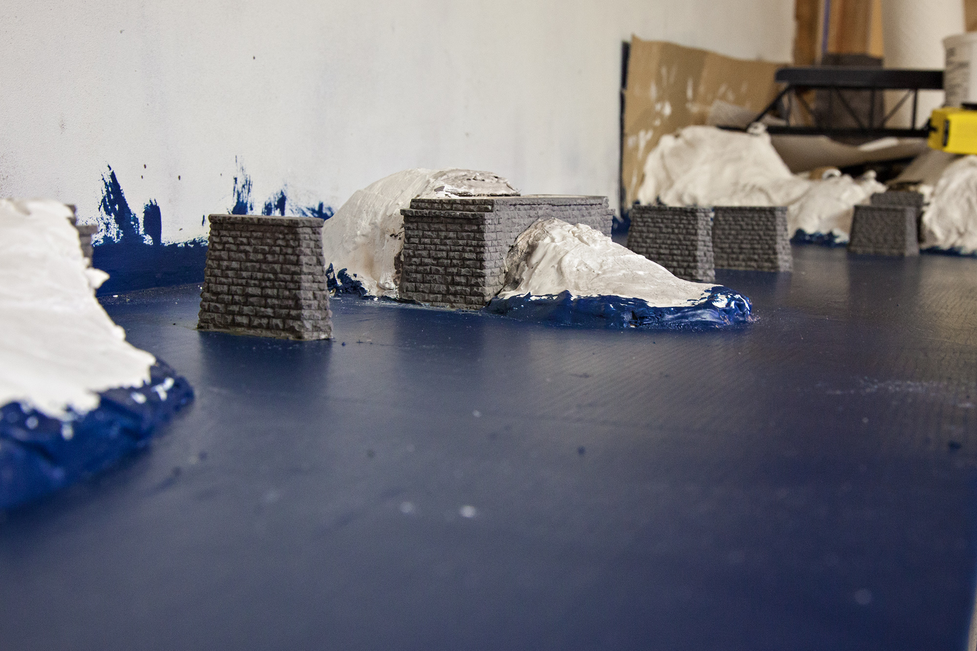
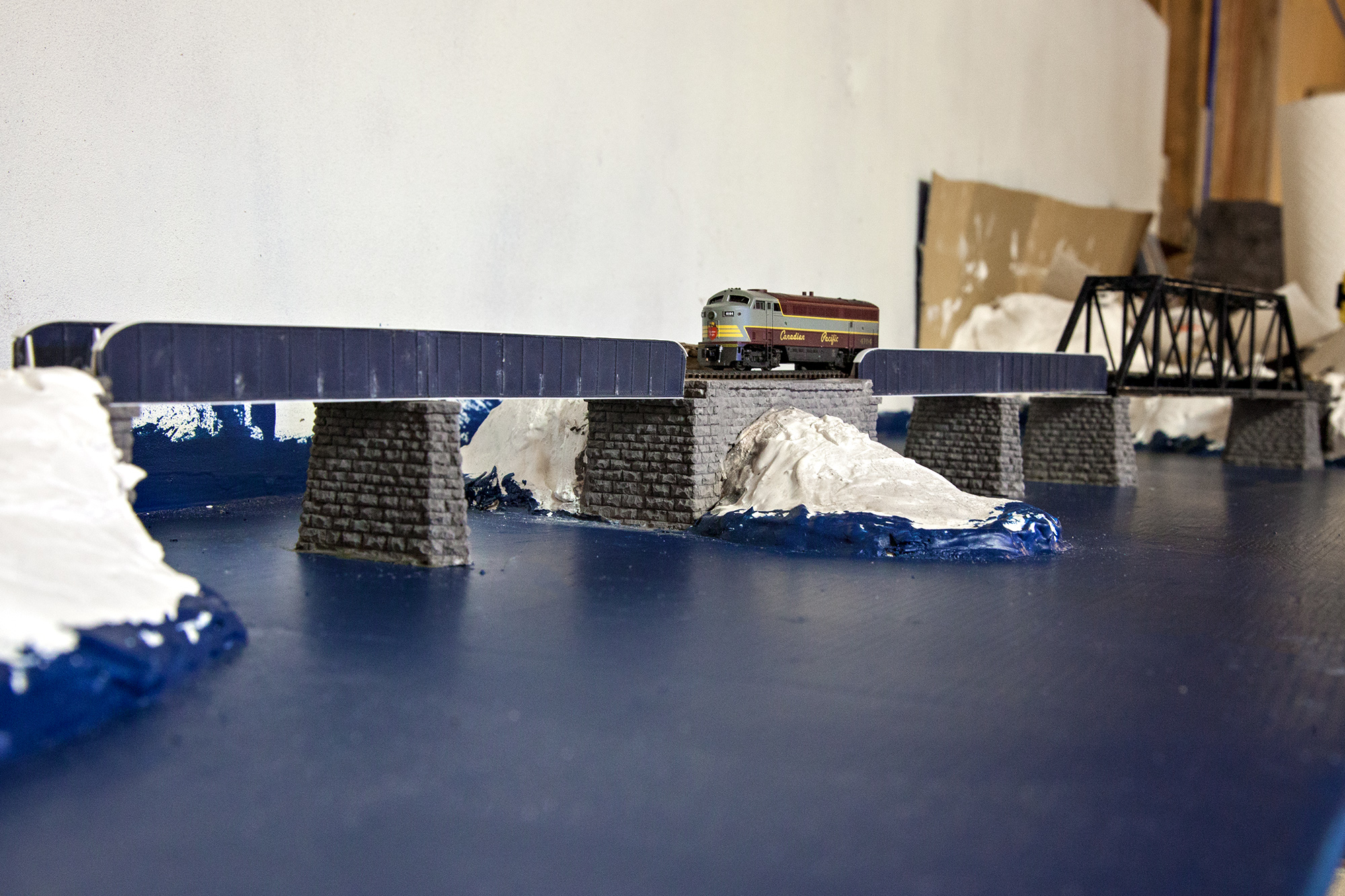
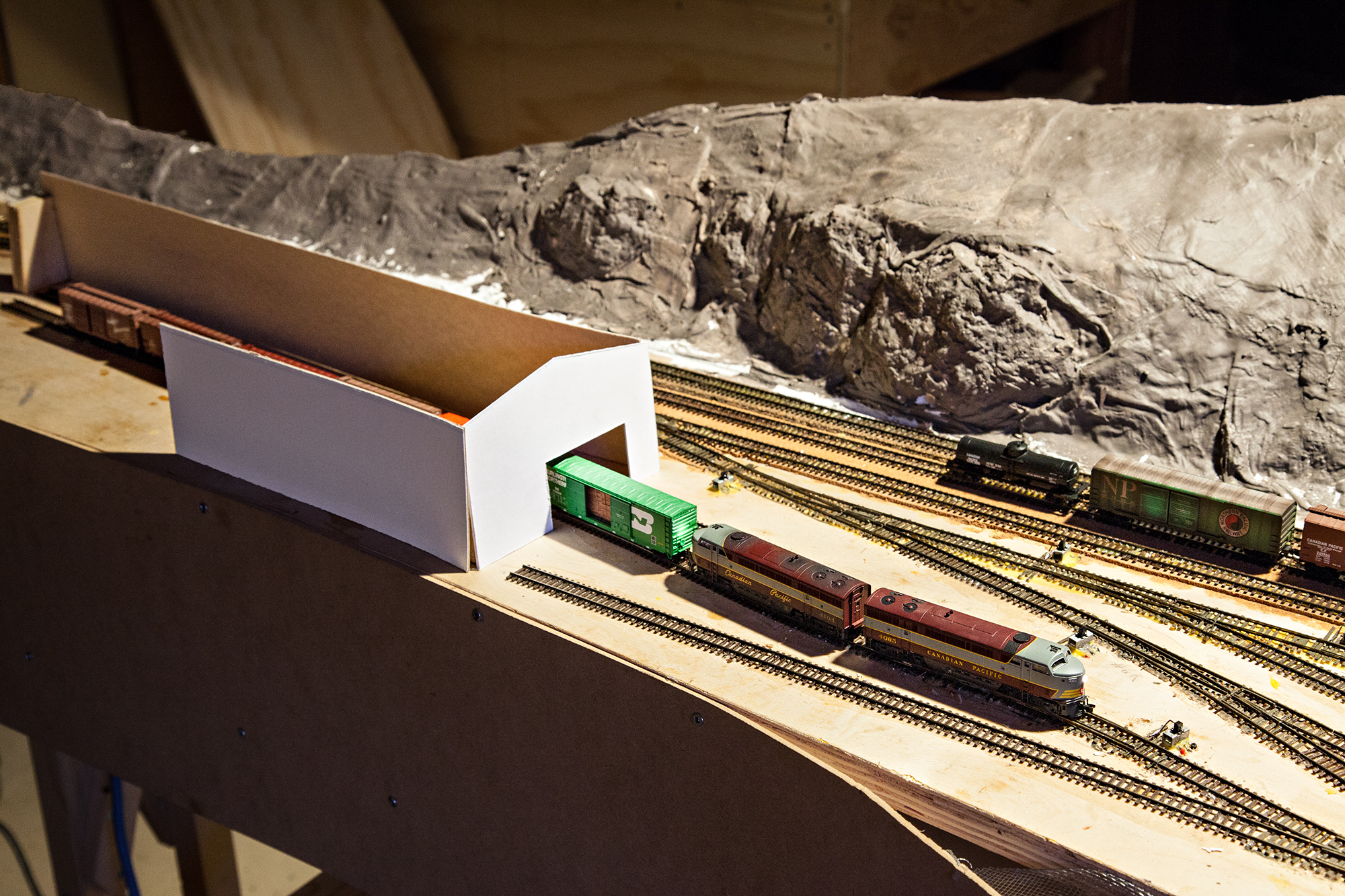
The shed is partially scratchbuilt, with stripwood sheathing and roof over laser cut bents, as cut by RS Laser. The background is by my partner Adrienne. The snowshed sits on a base carved from thick plaster of paris, shaped as it set to be the correct profile.

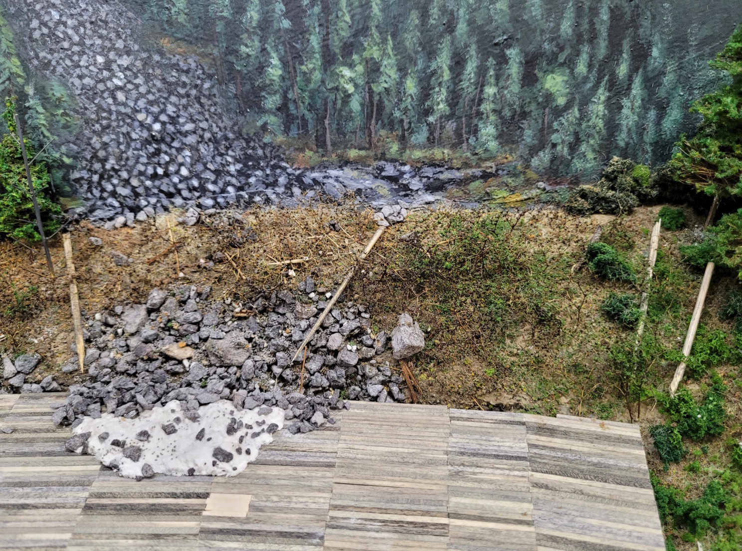
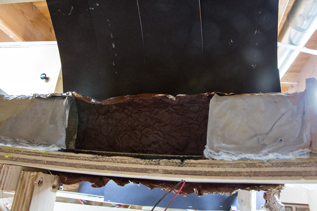
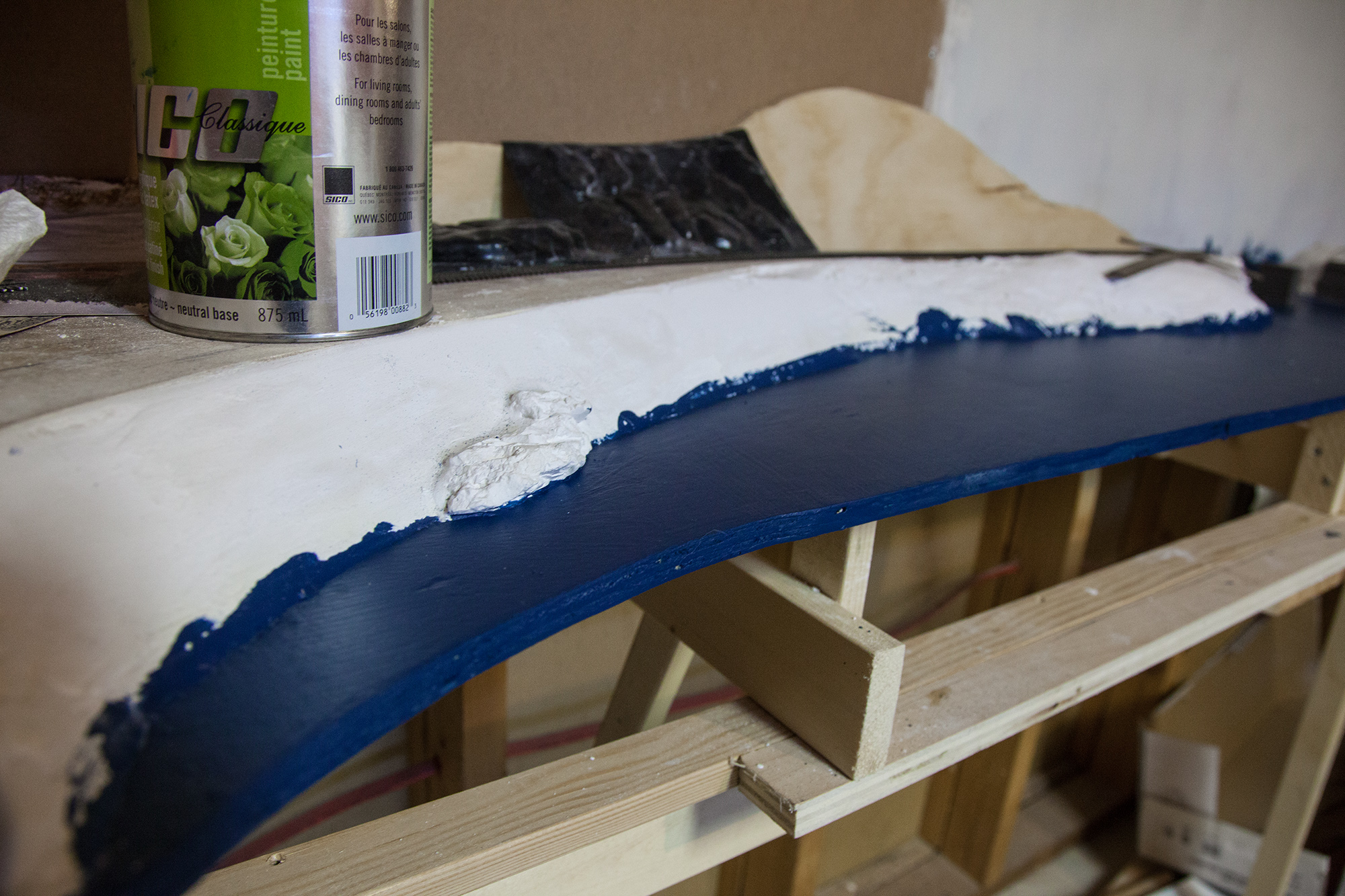
I’m modeling mid spring, so there’s still the remainders of avalanches on the slope and shed, mostly where they came to rest, at their thickest, but the slope itself shows signs of being recently covered – still brown since spring was delayed waiting for melt. This means a whole lot of brown tones.

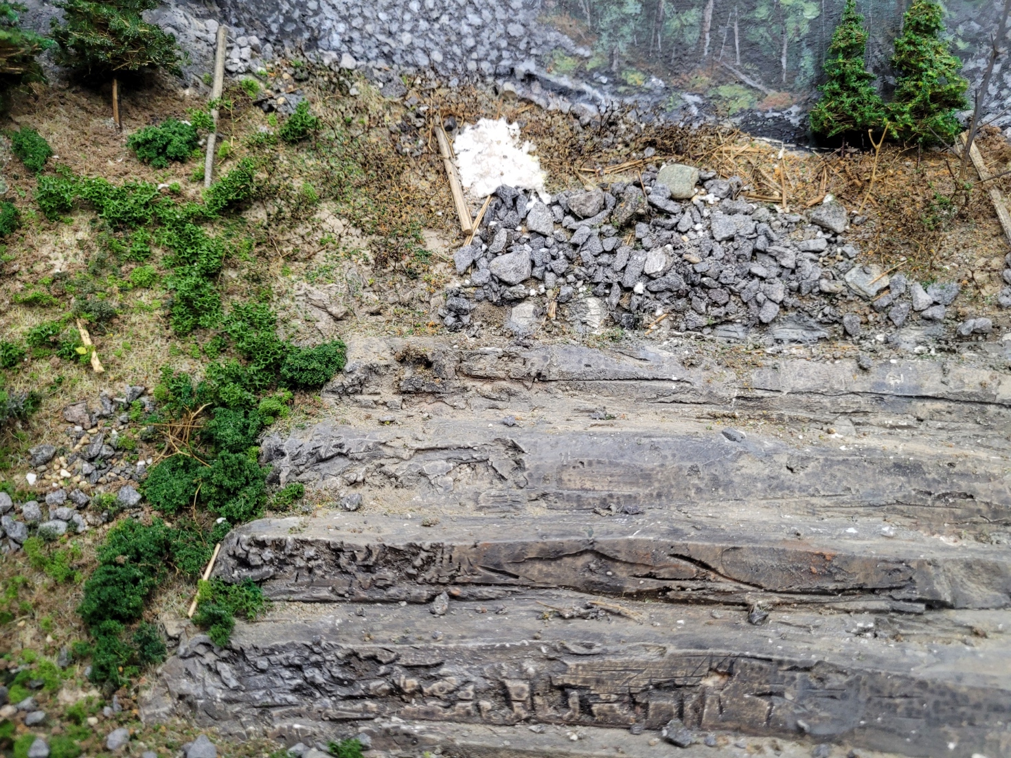
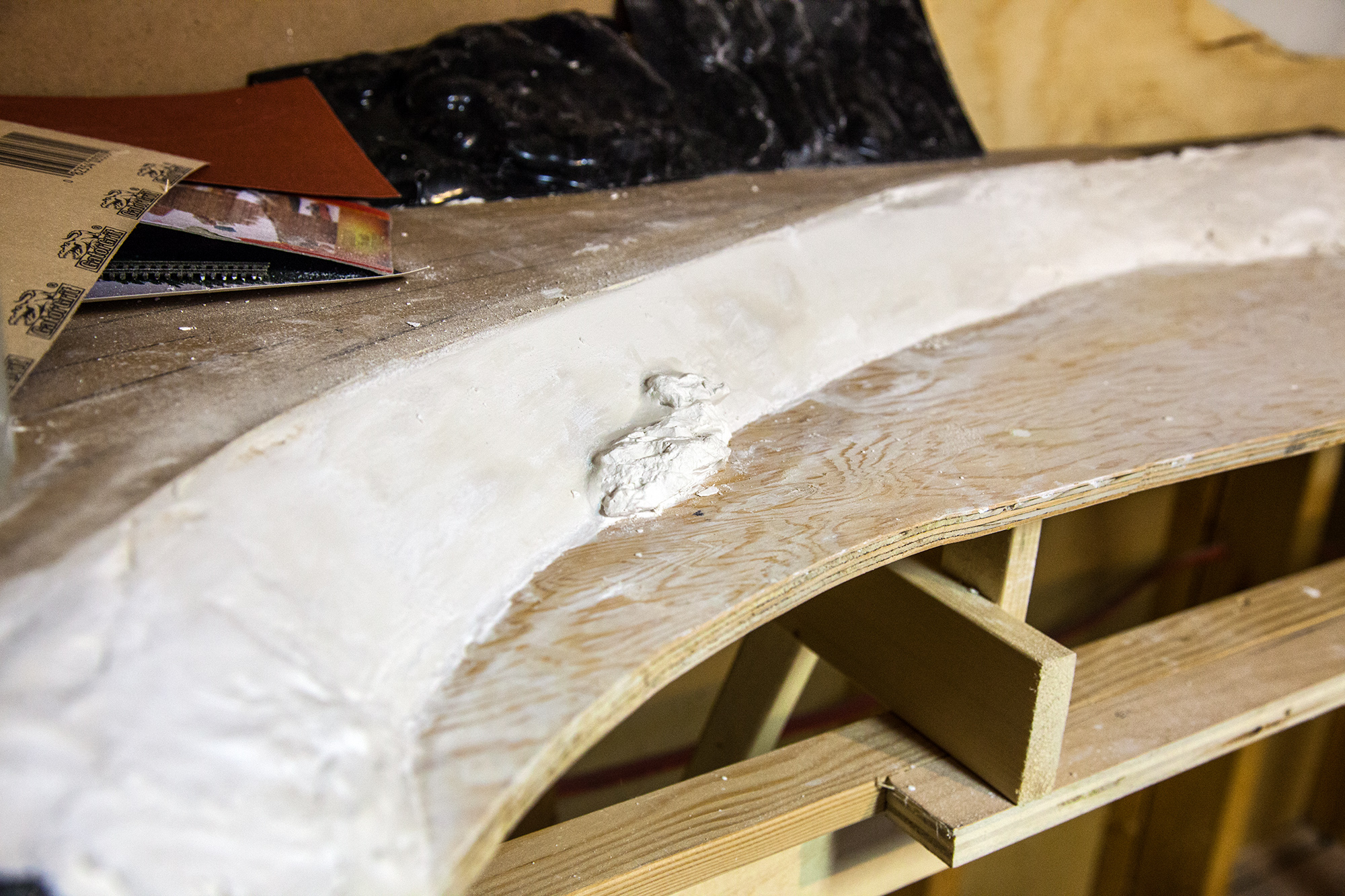
You can do whatever you want to get the desired base shape. I prefer to use plaster, and once I had that to my liking, I started off with a layer of dirt tone paint (varies by location) with varied random-ish splashes of both real dirt from the area and earth blend ground cover. (Either scenic express or woodland scenics are good.) After these were dry, I sprayed a good layer of 1:3 white glue:water over the whole area and sprinkled some random rocks and dead static grass (by hand, no applicator) and did a little finger finessing to get it pointed down the slope if it looked wrong. The top layer were the bushes that are present on most avalanche paths – protected and weighed down by snow, they’re not demolished by slides the way trees are. I used Scenic Express Supertrees that I spray painted brown. On the sides of the slope, I sprayed a little extra glue on them and sprinkled a bit of fine green ground foam on to simulate fresh buds. Either side of that, there’s an abrupt line of mature trees that haven’t been touched by sliding snow. At the bottom is bare rock, but that’s specific to my location with its shed – you will want scattered rocks brought down by the avalanche around, but not necessarily exclusively. Definitely lots of dead trees – whether the packaged ones by Woodland Scenics or the ones I made from both Supertree trunks or bamboo skewers.

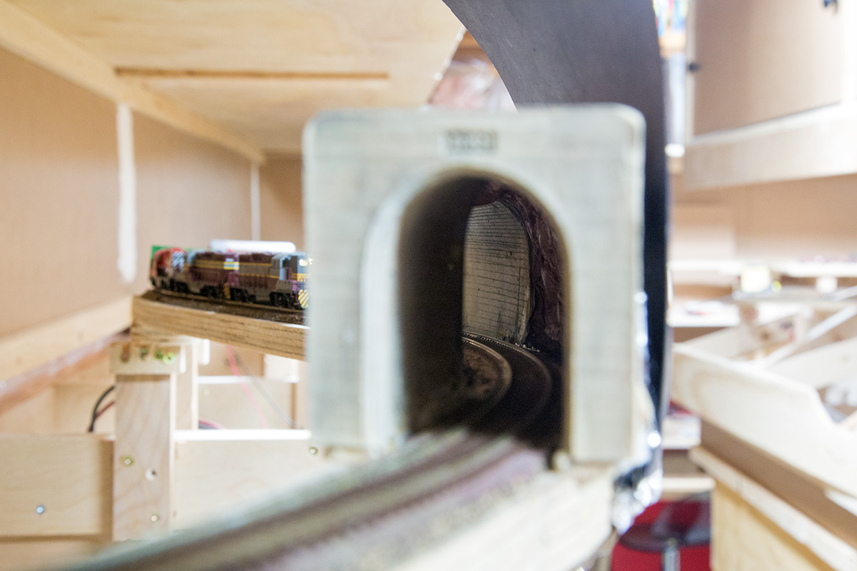
Now the piece de resistance! Leftover snow. Way easier than it looks. Grab some sculptamold (probably specifically due to its light yet clumpy consistency, can’t think of any substitutions) then press some rocks into it and shape it vaguely to where you want, then spray it with water. When it’s fully wetted you can tease it a little bit into more the shape you want, but you don’t want to do too much and make it lose its lumpy texture. After it’s dry you can wash a tiny bit of brown paint (raw umber-ish) onto small spots to give it that dirty texture, but VERY SPARINGLY.

And voila!

Quick update – February.

Prepare to be underwhelmed! I’m swamped with preparations for an upcoming bridal show, and have started doing real estate photography part time to bring in a bit more money. However, I did find a bit of time to do railway work in the past few weeks.

My goal is to have an operating session with 4 or 5 people in mid-March (after the aforementioned show) so I set up JMRI to route my cars and print switch lists – Needs more testing, but it looks like it works well! I’ve also created a new timetable and train instruction sheets, and I’m working on siding diagrams and dispatcher sheets.

The new timetable is meant to be printed on a double sided half-letter size piece of cardstock so it’s easy to carry. It’s for smaller sessions so I chopped all the trains that aren’t really completely necessary. Have a look!

Kootenay Division timetable 93

To accommodate this, everyone needs to know what time it is – I own a mix of NCE Pro cabs and utility throttles, and only the former has a time display. I got these great fast clock kits from Circuits4Tracks – They’re the cheapest on the market in kit form with the Canadian dollar down, easy to assemble, and have great customer service.

There will be a fast clock at Nelson (visible from Grand Forks and Castlegar) and at Farron (visible from Creston) as well as in the dispatcher’s office in staging.

20160225_113611

Additionally, I put in the plaster hardshell between Farron and Fife because it looked way too lame without it – Hence the last article about tunnel liners.

So, some crappy cellphone photos!

Passing the pond at Paulson

20160208_230037

Rock walls high above Christina Lake

20160130 3

Anyway, I’ll see what I can do before then – Something tells me I won’t have turnout control in for Nelson or Midway for the convenience of my operators. C’est la vie.

How to build tunnel liners: Concrete and rock

Spoiler for the next big post: I’ve been adding a lot of scenery base in. I decided to make my life MUCH easier and put in my tunnels, weathering and all, before the hills above, and I’m very happy with this strategy!

The prototype Paulson tunnel is 365 feet long through a nose of rock that shuts McRae Creek into a tight canyon known as Paulson Gap. This is one of my favorite spots on the Boundary subdivision, as it contains sheer rock faces, a tunnel and a snowshed in a few hundred feet of track.

The tunnel itself has poured concrete portals dating back to the 1940s. These continue about 30 feet back into the tunnel or so, where it reverts to blasted rock.

IMG_4896 IMG_4901

For the portals themselves, I used Chooch concrete portals with the top trim cut off and the corners rounded to mimic CP’s very utilitarian method.

Here’s where I got clever.

I made a form to act like the wooden forms the concrete would have been poured into. This form was made out of a dollar store ‘for sale’ sign with lines scribed into it with a somewhat dull exacto blade and a ruler at (roughly) the same points they are on the portal. Then, using a hot glue gun, I temporarily attached this form to the inside of the two tunnel portals. This ensured that it kept its shape, although the tunnel is much longer than that!

20151231 1

I had some clearance issues, the tunnel being on a curve combined with the narrow portals caused a slight rub from my test autorack. In the end, I changed the shape of the liner from a rectangle to a parallelogram so that the end away from the portal was higher. This solved the clearance issue.

20160103 1

With the form ready, I soaked some paper towels in a slightly runny plaster of paris mix (since they don’t carry hydrocal within 500 miles of me anymore) and draped them over the form, making sure the plaster was worked into every nook and cranny – though the end result says I could have done a better job!

Removing the form yielded a look that was almost perfect. The transition from portal to liner could be a bit smoother, but I ended up filling the gaps with more plaster. Then I painted it with a mix of mostly unbleached titanium and raw umber, following it up with washes of both unbleached titanium and black. (Couldn’t find the india ink)

Here’s two photos before the patching and final wash:

20160105 1 20160105 2

Next, I was going to just use black construction paper for the rest, but as I was putting it on I noticed that you could tell by looking through the tunnel as it was short enough that you could barely see the other side! The prototype is quite a bit longer, after all…I was all ready to start carving some plaster and was talking to my dad about how he did his tunnel liners with crumpled aluminum foil molds when he said “Why not just use the foil?”
Freaking. Genius.

This was seriously SO EASY. Crumpled a sheet of foil, spray painted it with some matte oxide red I had lying around, shaped it, stapled and hot glued it onto the existing liners (which were glued down by this point) and voila! It looks SO much better. It’s hard to show in photos, especially since I can’t get a tripod in. It’s only on the outside of the curve, since you can’t see the inside from any reasonable angle. There’s construction paper over the top to prevent light entry, and it’s attached with push pins to allow easy access in case of a derailed car.

20160107 2

Seeing the light shining through from the other side is nearly unreal in how good it looks.

20160107 1

Can’t wait to get that hillside built over it!


20160107 3

Until next time, highball!

Kootenay Division video series launch – A conversation through time!

Hey, everyone. I’ve been working on this huge project all year and will continue to for the upcoming year. I’d love it if you would all subscribe to it! The premise is that every Wednesday I upload a video taken a year ago and every Saturday I upload a video taken that week, and converse with myself about all manner of things.

It’s called Past Matt/Future Matt.

First Past Matt:  http://www.youtube.com/watch?v=ZBvm4qeKzuA

First Future Matt: http://www.youtube.com/watch?v=jwnKc_MBJS4

Subscribe!! www.youtube.com/subscription_center?add_user=kootenayvlog

Thanks in advance, please enjoy this 104-video long series!

How to build roads. Poorly.

Well, I tried. I took the best looking ideas for making a road and crapped all over them. I took the techniques from this page, because I absolutely loved the way they looked: http://www.telusplanet.net/public/crowley/ashphalt_roads.htm

Let’s follow what I did…

Step one was to add foam board. I got mine at the dollar store, 3 sheets for a dollar. I drew the curves freehand, though it wouldn’t have been much harder to use a radius stick thingy like I use for my curves.

20130414 120130414 2

Once cut (Don’t use a dull knife, you will rip the crap out of it!) I cemented it down with wood glue. I love wood glue.

This road is about 25′ wide, which is a good real life width sans shoulders, similar to the actual road that goes to Celgar.

20130414 3

Placing structures in their final positions, I could cut around their locations.

20130528 1

So far, so good….now it’s time for the plaster coat! The track is masked, and the outer grade crossing pieces are in place and masked on top and the side. This is where things begin going awry, however.

The link says to paint the tinted hydrocal on. I decided I wanted a smoother road, so I used a putty knife. This made it far too thick! WHOOPS. It was also hard to get rid of some of the ridges, so I decided I could sand it later. Sanding plaster? Avoid it if you can. Some of my track is still white despite my best efforts.

It looked fairly good…

20130528

…And then it dried.

20130602 2

Wait, what?

Yeah, it kind of turned nearly white. And I have no idea why. It appears that only happened where I smoothed it with my finger, but that’s PRETTY WEIRD.

It was at this point that I realized that pulling the masking tape off the sides of the outer boards left a fairly sizable gap. That’s no good! So I masked just the tops this time…

20130602 5

WHY IS IT SO LIGHT I CAN’T SEEM TO GET ANYTHING RIGHT MUUURRHHH

20130602 6

YEAH THAT’S RIGHT YOU TOO BRIGHT YOU GET PAINT HA

20130606 2

Getting closer! Add in a little bit of drywall mud, paint carefully, aaaand…

20130608 1

Alright!

20130608 2

YEAH! It’s not perfect, but I’m happy for the time being!

So, you might be wondering about the crossings…the mainline crossings are straight Osborn kits, and the throat of the mill is made of Blair line one lane crossings. They fit in quite well with my road width, although I’m not sure I like the look of two pads together. Oh well!

I weathered them from new wood to dirty by first staining them with some leftover dark wood stain I had left over from photo boxes I made (walnut or something, I don’t know…) followed by a couple washes of India ink once they were in place. Don’t be deterred by the stain’s water-repellant nature, it will soak in eventually!

Sooo…yeah! Take what you can from this!


I should really write one of these.

Geez, I’ve been putting this off. Why? I wanted to provide finished stuff, not updates! Too bad, nothing’s finished. Where am I? Wellll….

Just after my last post, I fixed up the track going from the Boundary sub to the Rossland sub main, which is the straight through track of the wye. Things kept decoupling on it because the transition was too steep, so I pulled it up and sanded it the hell down – dumb me also forgot to feed it! All is now well.

20130123

A few tracks over, however, more problems arose. The track buckled and an earlier attempt was made to secure it, but alas, it only made it worse. I had to pull it up and sand out all the caulking from underneath it. Remember, when securing track to a surface that isn’t perfectly level, make sure to secure it VERY securely.

20130124 1 20130124 2

I bought a whiteboard and whipped up a timetable for it. I’ll do an actual printed timetable eventually, but I need to learn how to use design programs first.

20130120 1

So that’s it for January…Awaiting resources, I made no posts and no progress. A week in, I realized something I could do – Though I had yet to calculate where to put the backdrop and scenery behind McCormack Creek bridge, I could totally divide it into two sections, doing the front first, leaving room to put the bridge in! First I put in a good solid support for the fascia, which is extremely tall to accommodate the bridge. This is comprised of 1×4 salvaged from the 10 year old scrap pile, some 1x3s for vertical support, and a failed cut for the helix to perfectly match the curve above.

20130210 1 20130210 2

Next up were the scenery supports. Working from my CPR plans, printed to 1:160 scale, I positioned pads for the piers at the right points, and cut out the exact profile of the valley. How ridiculous is that?! I also put profiles in a few other places for good measure.

20130215 1

At the same time, I set up a new cut for Castlegar, one that shall have smooth sides. It’s all glued, supported in obvious ways.20130215 2

After that I didn’t get much done for a while. I ended up soaking those 6 deluxe innovations chip hoppers in brake fluid (prestone dot 3) which worked very well, if apparently toxically. I filtered out most of the large bits of paint floating in it by running it back into the bottles through a coffee filter. This clogged up pretty badly, and though the first bottle filtered through in about half an hour, the second half of the second bottle took four days. FOUR FREAKING DAYS.

Oh yeah, then something pretty cool happened.

I GOT A JOB.

After over a hundred applications, perhaps closer to 200, I finally found SOMEONE who was hiring. That’s awesome. I won’t have a big budget, though, since I did my fiscal planning and my budget is much the same as before. Oh well!

My current project, besides the planning for the upper deck (which is finally gaining traction) is working on the helix.  I’m offsetting the top by 2.5″ to allow some room for scenery as it curves around the top, so I’m planning the tie-in for the upper deck. This is very exciting. I removed the last section of the helix, leaving cool hanging track while I added in the spacer section.

20130326 1

Having taken off the masonite I had previously wrapped it in allowed me to become acquainted yet again with how terribly skewed my supports are.

20130326 3

Also, I don’t believe I’ve posted a photo of all the feeders going into the bus, so here it is:

20130326 2

Maybe someday I’ll get some ty-raps and tidy it up.

Next up, I positioned the section and found out that GUESS WHAT there are problems. First off, it doesn’t make it to the next support. Not a huge deal, I’ll deal with it. The best way to deal with it, unfortunately, is to add another inter-deck support like I’ve done in many places. That doesn’t work because the inside of this subroadbed strip is outside of the outside of the next one down.

20130326 4

In the end I figured out that the inside of the top should line up quite well with the outside of the next one down, so I screwed and glued a 1×2 to the outside of the second to top level and the underside of the top level. It’s now fairly solid, but I’ve got more tweaks and a cool idea to put into practice.

20130326 5

Well, back to work! Someone’s gotta make a bunch of cash for flextrack – oops, I mean, a house. I’ll try to come back quickly!

Kootenay Lake and Taghum bridge

One end of the layout that I feel I should really get in shape is the section just outside of Castlegar – the long set of bridges over the Kootenay River at Taghum, giving my wye a leg of another 1000′. Plus, scenery experience is great! I still don’t like rockwork. Really unfortunate.

To start, I had a wire mesh section already plastered in at the west end of Nelson yard (nothing to the east will exist until I raise the funds to finish the other 3 walls of the room) but I was unsatisfied with the embankment. The prototype’s lakeshore at this point is fill, so it’s a fairly uniform bank. To achieve this, I took some paper similar to bristol board, cut it to size (Pythagorean theorem style) cut slits in it so it could bend around the corner, and taped it down before applying plaster.  Once the plaster was dry, I sanded it so it would be a smooth base. Later on I’ll put a layer of ballast on it. The rock castings are not secured in place in the first photo.

20121205 1

After:

20121206 1

After painting the lakebed with latex acrylic house paint:

20121214 3

I hope that blue isn’t too blue and light.

A note about the lakebed: SAND THE PLYWOOD FIRST. I made the mistake of doing a light rub, but you really really REALLY need to give it a thorough go-over with a power sander to make it flat enough that the grain won’t show through. I did two coats of paint, sanded the paint and added a third and it still shows. You’ll see in the following photos…

One nice thing about such thick and rubbery paint is that if you have a backdrop that has a tendency to move away from the wood, leaving a place for liquids to flow later, the paint will seal that shut. If you’re wondering why I’m not worried about paint all over the backdrop, it’s because we’ll be putting digital illustrations in there later.

On to the bridge. The piers were causing me problems as I couldn’t get them cut just right until I had an idea: Use the mitre saw and shim it. They’re tapered towards the top so I figured out exactly how much skinnier the top was, divided by half to get it straight (close to 1/8″)  and then rotate the saw to an angle matching the base of the casting to get that right. I also had an extra scrap behind the casting so it wouldn’t skew into the hole behind the cutting area. It worked! Now I have two beautifully straight piers and two…not quite so straight ones. I painted them with a mixture of white and black (guess who doesn’t have any gray?) with a touch of a reddish-brown colour called burnt sienna. I secured them with wood glue, although I did scratch a hole in the paint below each pier to allow them to bond with the wood. I recommend doing this!

20121214 4

Another thing I got done was the Central Valley 150′ pratt truss – it’s not perfectly to prototype but it looks damned good. I’m going to paint all the bridges a uniform shade of grimy lack and then weather them before putting them in place. Still, it’s fun to simulate!

20121214 5

Great! I like progress!

Now one thing that was bothering me recently was the sawmill. I couldn’t decide whether I wanted a loading building (thereby making it look like a bigger industry) or just a covered loading shed (like a prototype at Slocan City). I started mocking up the building, but eventually realized what must be done, at least with the help of polls on several forums. I moved the track closer to the aisle to leave room for a loading platform behind the tracks, instead of blocking them. I think I like this!

Before:

20121204 1

After:

20121214 2

This scrap of foamcore turned out to be the correct size for a loading dock, if I decide to have it at boxcar door level.

20121214 1

That’s all for this week, in the future I’ll be working on getting the bridges in place and rockwork around the tunnel at Labarthe. Ciao!


Tote dat barge, smash dat ridge

On today’s episode of “What that crazy guy is doing”, we find him in his basement with a large mallet.

Oh, did I get ahead of you? Sometimes I do tend to skip to the fun bit.

On my last blog post, I was adding a road and a hydrocal base. This I enjoy. Let’s pick up where we left off…

After a day or two of spreading chunks of plaster around the house, I had pretty much all the hydrocal in place except for between the west switch of Nelson and the backdrop. At the same time, I put rock castings on using thicker hydrocal as a sort of glue. If you like sculpting hydrocal (I don’t) you can use it at the same time to make the rocks blend in better by creating more rock face around them. I plan to do this with slower drying sculptamold later. I do not enjoy creating detailed cliffs.

I think that extra inch or two all along helped a lot.

Meanwhile, I decided a high cliff face like there is right beside the Keenleyside dam would be fab. I hope I don’t end up tearing it out. Another thing I’m doing, since hydrocal costs about a fifth as much as sculptamold by weight (probably a twentieth by size) is rough in the various protrusions so only a thin coat of sculptamold is required.

Also put in a few bits up the line past Labarthe.

Now we come to the precursor to the smashy bit…

That steep face on the left that just doesn’t look right? Yep, that’s the one. Several reasons it needed to go:

  1. It was too close to the tracks to put any rock castings on
  2. Didn’t work with the lay of the land
  3. (most importantly) there was no equivalent prototype cliff, just a big ol’ load o’ trees.

That brings us up to speed. If we go back to this post we can see what the base looks like, especially in this picture. I took out the cardboard support and let it slope gently, adding some compression to the hillside which I’ve lately found is nice.

I also winged it with laziness on the lake side of the track, since it was too steep. I wadded up some newspapers, tried taping them down unsuccessfully, and ended up just plastering over them to give a rough shape and then shaping it more as the plaster dried. I’m absolutely shocked something so lazy worked.

Finished avalanche slope – I mean hillside:

In person, it’s miles better. Lumpy, but better.

I also realized that operations and videos would be a lot better if I had somewhere for trains to go once they were past the tunnel, so I added another mile of mainline run by saying “to hell with ideals, I’m building a temporary bridge”

So I cut a wide piece of plywood in the hopes that it would stop derailed rolling stock from falling off, and since I was out of flextrack, patched my 3 longest scraps together and caulked them down right on the plywood.

That gives me some sort of staging…problem is, 81 can trundle right up into it, but staging an eastbound? Have you ever tried to back an N scale train with a mix of body and truck mounts up a steep grade and around curves?

Let’s just say tomorrow’s project is adding some scenery around the bare bits so that my trains have somewhere to fall.

Additionally, I’m in an art show this weekend, so it’s amazing I’m doing anything down here at all. Procrastination? Nope, I’m not using real life as an excuse not to play with trains!

I totally know what I’m doing.

Deck’s pretty much done. All the boards are down, and all that is left are about a thousand screws once that foot of snow disappears. Waiting for that, I got a few things done. I apologise for the mess in the photos, it’s a symptom of my laziness.

Big problem: Sawdust. Sawdust EVERYWHERE. The best way to make a model railway is to build all the benchwork, and then get on the less dusty things. Too bad I’m not doing it that way.

Biggest offender? My mitre saw that spews everywhere. Look at this:

Soo…I built a workbench just for the saw, using all the bits of plywood I had lying around as well as a bed that I had made for my grandmother to sleep in. Said bed was made from leftover bits of deck. Reduce, reuse, recycle!

So here it is. Only thing I bought new were the legs, and 4×4 cedar, while expensive, smells so lovely I left it in my car for a week.

The hood takes care of 90% of the sawdust. Wunderbar! You can also kind of see the backdrop that we ‘finished’. My artist has decided that paint can go wash itself down a sewer, and we’re doing the rest of them digitally.

Ironically, backdrops lead us on…

First thing I did was redo the abutments. There’s $40 I wish I hadn’t spent. MEASURE IT RIGHT THE FIRST TIME OR BE DUMB AND POOR LIKE ME. I somehow neglected to think about the height of the step that the bridge would sit on verses the height of the top, and there wasn’t really any way to fix it and have it look like it was anything but some weird concrete patch job at the bottom.
Next up  was a bit of scenery. Why not try a lattice? Oh, and throw some random bits in there too…I totally know what I’m doing.

Edit 11/16: Don’t use cardboard for a lattice. It’s far too thick and lumpy to work with. I hope I’ll be able to work with this section but there’s a chance a later post will show a conspicuous hole here.

I had to replace the original raised plywood because there was no way I was going to get anything acceptable out of it. So, some 3/8″ plywood with masonite glued on for road? Yes, I think so. I’m going to learn how to actually make stuff in sketchup and have shapeways print this bridge, and pray that it looks good.

Also did the bit between the tracks and Kootenay Lake/River. While in the area I took about a trillion photos of cliffs and rock formations, so I’ve got this pretty well in hand.

Oh yeah, that’s when I realized I had a problem…I can’t do that backdrop later, I have to get it done and in place first. Damn you, immovable load bearing wall!

So I made a road instead.

I’ve been struggling with the roadways in the pulp mill, seeing as there isn’t room for anything realistic. Or so I thought…the upper deck will protrude quite a distance beyond the lower deck at this point due to the 1-turn helix that will both simulate the 1km long Bulldog tunnel and get the track over the nod-under. I realized that I could jam the road in here comfortably if I redid my benchwork a little bit. I replaced 4 joists with longer ones, and constructed a 20′ wide road out of 1/2″ ply. My concept is that it will kind of disappear into the trees. I really hope I can manage that.

Here’s the current plan. Anything to the right of the left-most grade crossing is just roughed in.

Here’s to hoping it will look good!

Bridge that gap.

Now, you’re probably wondering “Why aren’t you done your deck yet?”

Well, the answer is LOTS OF REASONS AND SOME OF THEM ARE GOOD.

See that? That’s weather. That’s my #3 cause of delay. It allowed me to work a bit, however.

First thing I did was work on the island at Taghum. It’s a slab of plywood on top of a couple of risers surrounded by plaster and chooch castings.

I figured that I could fill the gaps with hydrocal and carve it later. I either don’t have the tools or the skill, but either way it didn’t work out.

Anyway, it looked good once it was painted. Used a combination of black, white, and burnt sienna thinned out a bit to be a bit wash-y and not entirely blended to give some variety. The plan is to add some white washes to give water lines and highlight the mortar.

Looks nice? Well, I have to redo it. Because I screwed everything up. Such is life! I’ll get back to that later.

I also put in the benchwork for the west switch of Nelson yard, right up to the section edge. The next section will wait until the drywall is in place…if it ever gets built.

Ignoring the ping pong ball assortment, this is what the construction is like. I only used risers, I didn’t bother with 1x1s. The plywood you see is the river (well, lake at this point) basse and the risers above it are for the subroadbed. Only one subroadbed riser comes from the joists, the rest come up from the lake. Anyways, on top of that I decided to use cork strip past the last turnout in the yard and masonite for the yard base. There’s no difference on the prototype in railhead elevation inside the yard so that gives me an excuse to be lazy.

I drew all the track lines on the board before I cut it, made it a lot easier.

Unfortunately, it does end abruptly, but not at the most awkward point. WHOO PLANNING!

Anyways, leaving that for a few months, I’ll get back to the bridge.

I built it using Micro Engineering 80′ plate girders cut to the proper length. I then clamped all 8 girders between a pair of toonies (Perfectly sized round $2 coins, Americans) and filed them until they were rounded like the prototype. Once done that, I used 0.010×0.125″ strip styrene to add a new stop and bottom to the girder. Braces were made using 0.3″ styrene cut into 1″ wide and 1/4″ tall strips to support the track at near the prototype height. After that I eyeballed the bracing and just winged it. For the bottom bracing, the first bridge I winged it and made something beautifully abstract. Second bridge I planned ahead and it looks…better.

Let’s have a C-liner and some Micro Engineering bridge track for scale, shall we?

Well, I’ve done worse. Anyway, the problem at hand: The bridge feet are just under 1/8″ high, and the gap between the bottom of the bridge and the piers is more akin to 3/8″. I’ve decided to use a spare pair of abutments (I accidentally ordered 4 pairs instead of 3) and recut them so the top and second step are at the right height, but the piers are up in the air. I kept the off-cuts and have glued them back together, and I’m going to see if I can recut them to be taller without them looking horrific. Wish me luck!