Layout redesign – Cranbrook to Creston

An operator at a session last year unintentionally unleashed a demon on my layout.

When are you going to put in Creston?”

When…when am I….well, first I have to figure out the track plan and proper operations, which have an impact on Nelson and Cranbrook. Looking into those, I realized I had a problem – the east siding switch of Creston was only about 400 feet from the west siding switch of Cranbrook. That was going to cause some problems! I decided to solve that as well as another problem at once by adding some run. But there’s no more room to expand the layout! Unless you think…. UP!

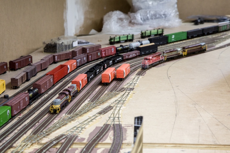
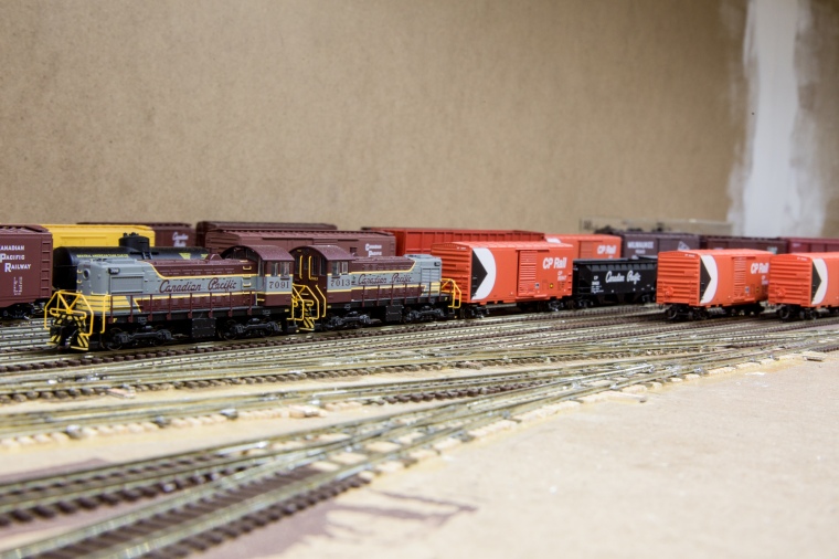
Here’s my Cranbrook, ca. 2017. It was in this configuration for less than a year! I had roughed in a middle level for stub ended storage tracks, approx. 2400′ long, for whatever I wanted to shove in from the non-existent helix that I had intended to connect the east and west ends of the layout with but never built or needed.

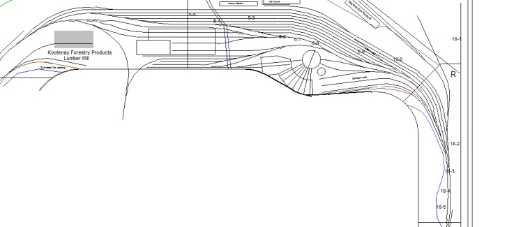
Here’s the old plan:

You can see the issue – this is compounded because operators have to walk around a fair distance to get from Creston to Cranbrook due to the furnace and water heater being in the way.

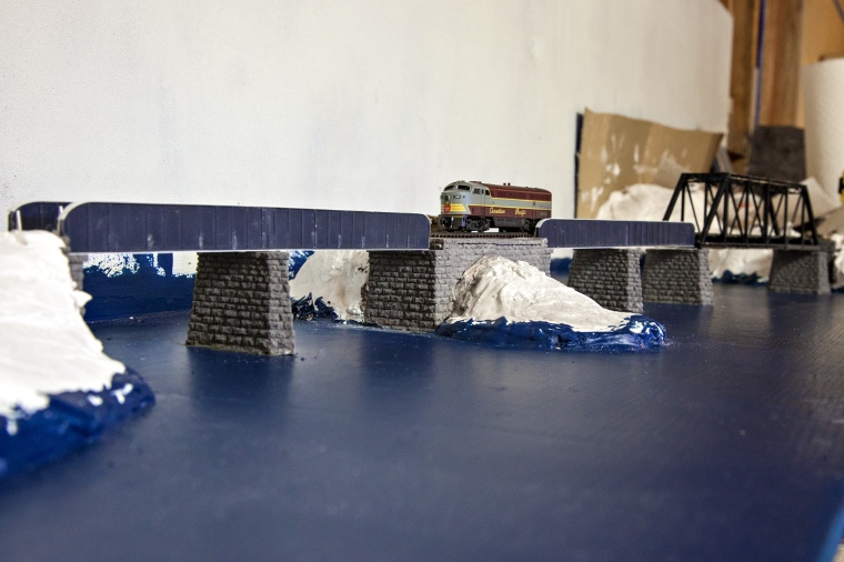
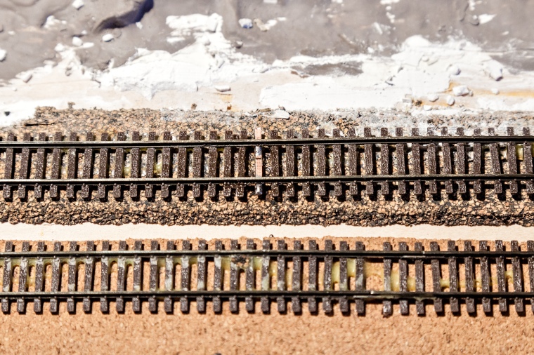
In real life, east of Creston, the line climbs up a maximum 1.25% grade up the Goat river to a summit at Goatfell before descending a short downhill to Yahk. There’s not too much on the way, the small town of Kitchener (station name McConnel to avoid confusion with Kitchener, ON, as the CP didn’t allow duplicate names on its system), but what really catches my eye are two features. First, east of Erickson (a stone’s throw from Creston) the railway crosses the Goat river’s box canyon at the town of Canyon (Original!) on a pretty darn nice bridge.

Canyon-Lister road also passes over the river and under the rail line, as you can see.

Up past McConnel, the line goes around a pretty nifty horseshoe curve that’s hidden by trees. I’ve never seen a photo of a train on it, but it’s plainly visible on google maps.

https://goo.gl/maps/bbGrt95h23s

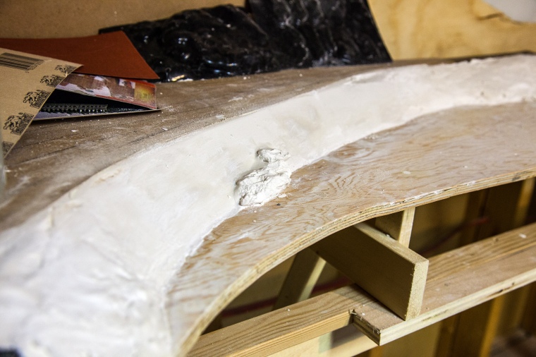
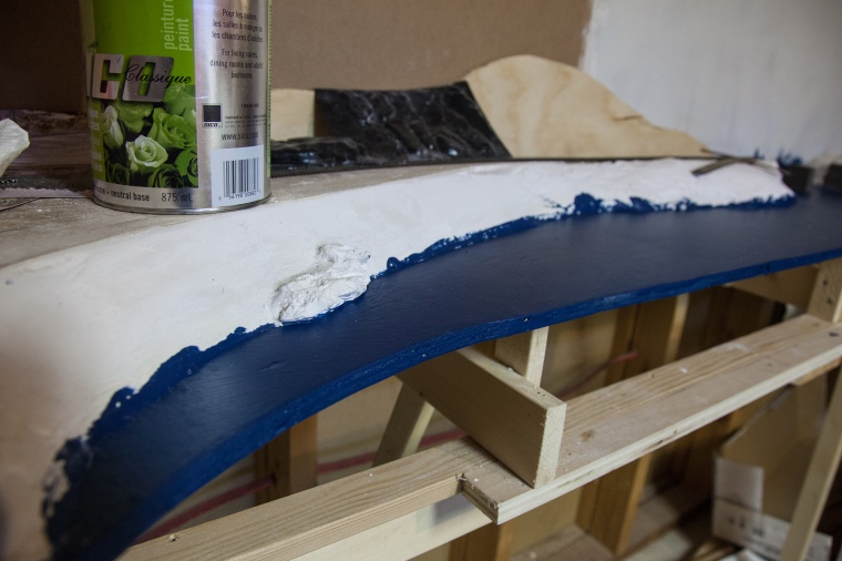
I realized that I had plenty of space to incorporate both of these, but I felt like I needed something more in the wide scene. I chose to add a 15′ wooden trestle that exists up at Goatfell. It should be a culvert, but instead, it’s a great project!


I drew up plans to move Cranbrook from its current elevation at 0.5″ to 12.5″.  After some experimentation, I decided this was the minimum deck separation from the lower deck that would allow it to be scenically workable. This also left enough room to access Cranbrook under Midway. Here’s the new plan:

You can see the Canyon bridge on the original alignment (which was dictated by the furnace and studs) leading up to the horseshoe curve before going through a 2 turn helix to bring it to Cranbrook’s new height. The grade is 1.25% from Creston onto the bridge, going up to 2.0% about the midpoint of the room through the horseshoe – more on that later.

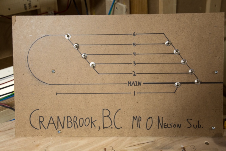
Up in Cranbrook, I originally designed it with 6 run-through tracks and 1 shorter stub track. I guess I wasn’t paying attention when everyone said that you need to design more staging than you think you need! I added 1 long and 3 shorter run-through tracks (800-1000′) and removed the stub track. I moved the reverse loop to the right side of the room, keeping it on the east end of the line, as the tracks in Cranbrook were now reversed east to west.

Building a wedding cake helix:

I wanted the grade in the helix itself to be as mild as possible. My other helix continues with the 2.65% ruling grade of the Boundary sub, but I didn’t want to have such a prominent grade be an obstacle to operations. (The other one is so on purpose)

The grade is 2.0% coming through the horseshoe curve, but lessens to 1.75% through the helix. Why? Two reasons. The ruling grade is in the curve, which means that if a train either can’t make the hill you’ll know right away, and worse, if it stringlines, it’s going to do it where you can easily get it back on the rails without screwing around in a well-designed and accessible helix.

With the grade being 1.75% throughout the helix, but that meant that the separation between levels was going to be 2.1″ railhead to railhead. That’s not a whole lot! I decided to make the helix out of a 1/4″ plywood base supported every 6-8″ and 1/8″ hardboard on top of that to join the plywood together. Take away another 1/8″ for the ties and rails, and that leaves 1-5/8″ clearance above the rail. Note that this is slightly more than the NMRA recommended 1-9/16″, but that doesn’t allow for fingers. I cut them in arcs from smaller pieces I had kicking around. I designed it as an upside down wedding cake style so that you can reach in from above as well as the side, making access much easier. The radius expands by 1″ every level, giving (as you’d expect) a 1″ offset from one level to the next.

I basically laminated the two layers together with wood glue and a ton of clamps.

Here’s an overview before I wrapped the outside in hardboard.

Moving the Cranbrook Staging Yard:

So I’m adding a couple tracks, does that mean I want to rip out the whole yard? No – and it’s designed sectionally, as is the rest of my layout. So why not take it apart and put it back together? Sounds easy! Of course it’s not. Coming apart went well. I used my ultra thin dremel cutoff wheel to gap all the rails first.

Took out all the screws, and she’s free!

I disconnected the wires from their terminal strips at the section joins and carefully pulled everything apart, making sure none of my additions were looped or stuck, removing the occasional piece of benchwork to free some wire or another until the section was free.

Then things started to get weird.

This just felt wrong! Anyway, those stayed like that for the next couple weeks while I tore out the old benchwork and put in new. Things were very messy during this time. I was able to reuse about half of what was there before, but other changes were too big and I had to add new L girders and joists.

One complication: My wider helix was closer to the wall than the original curve into the yard, so I have to shave a couple inches off that section, in a straight line. I clamped a 1×3 in precisely the right spot to keep the blade of my circular saw where it should be, and prayed that I wouldn’t destroy my track.

In the end, I only messed up the flex a little bit and broke one PCB tie on the turnout. Not too bad!

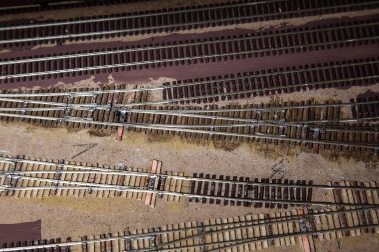
I added in 2 additional turnouts to this ladder as well as a small extension on the table to accommodate the 2 extra tracks. I put the turnouts in while the section was still loose, it was the easiest way to work and didn’t have me hunched into the corner for hours.

I also cut a new ladder of  3#8 turnouts in at the back. I chose 8s because the angle more closely matched how the yard came away from the wall.

Moving the yard over by those few inches also left me with a choice – do I move the whole yard over, or make it slightly longer? Might as well make it longer! It was easier on a few tracks to replace the flextrack to the next join rather than splice in a 4″ section. I added the other new tracks later in order to get the layout running faster.

Out by the furnace, I had to replace the dispatcher’s panel as it was soaked by a leak from the furnace humidifier that I didn’t realize was even on, so I built a sort of box to support both the Cranbrook reverse loop, the line up from Creston, and the new DS panel. At the same time, I realized this wall isn’t load bearing, so I removed a couple of studs. Hehehe.

Down the Hill to Creston

Let’s jump back a bit. Since the staging yard was gone and accessibility was at an all-time high, it was time to build the grade down to Creston. As I’ve done before, I used xTrackCAD to make the best use of my plywood for the cookie cutter roadbed. I don’t have that file anymore, but here’s one from earlier construction:

That jigsaw was a damn good investment.

Put them all up on risers, as I’ve done a hundred times before – I use shims and levels to make sure the height difference is correct between the risers, as well as to check the risers are level on top.

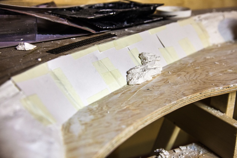
I left this gap for my tiny trestle. I hadn’t decided if it was going to be as small as in real life (it will be) so I left a bit of extra length and height just in case.

I didn’t use cork roadbed inside the helix, but I did transition to it before the visible run. I’m superelevating the curves using the masking tape method I’ve been using forever. Superelevation looks SO GOOD, GUYS.

I’ve made a change to the way I designed this part from the rest of the layout. Most of the curves on the rest are 18″. Here, I tried some variation, as well as adding a few longer straight sections. There’s an 18″ curve, a 24″ curve, even a 30″ curve! Believe me when I say it looks FANTASTIC.

I mentioned this was all because of Creston, right? While I haven’t yet finalized my design for it, I decided where the mainline was going to go – which isn’t where it was previously. I wanted it to be on a ridiculously wide curve. How was I going to manage that? Well, I decided to grab a piece of 1/4″ hardboard, clamp it to 2 pieces of lumber where the ends were, and let it decide the rest.

Mmmm. If I managed to get it close, that’s about a 110″ radius – a 4° curve!

It was at this point I took a 2 week break from trains to get married. (Sorry, not sorry.)

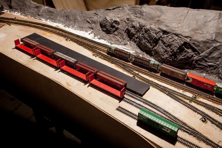
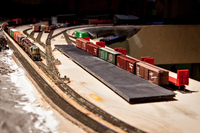
With that checked off my life goals list, I went back to lay track up from the Kootenay Landing bridge to Cranbrook as well as add in the 4 new staging tracks and reverse loop, put the feeders on, and ran 2 extras back into staging where they belonged!

See what I mean? These curves look fantastic.

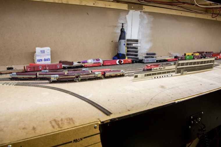
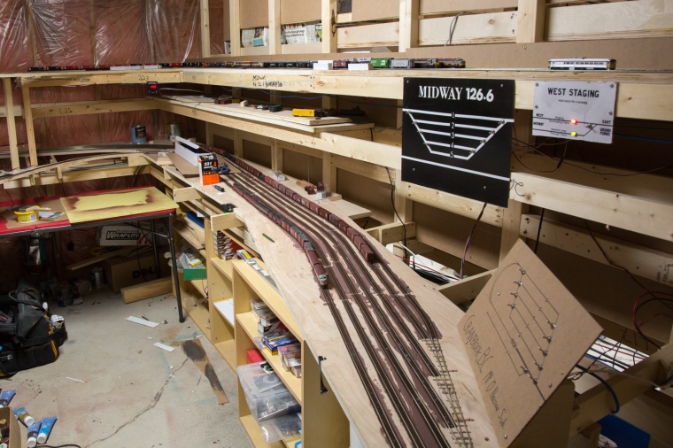
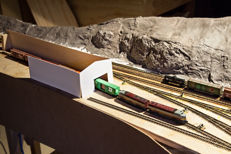
Gee, seems empty up there…

You can see the Midway panel kicking around where it shouldn’t be – that’s because it was too tall and interfered with Cranbrook once it was moved. I decided to make a new panel for Midway and make fascia for the staging in order to make it look a bit nice. I also had to make a new panel for Cranbrook. I reused the old bits from both to save myself from a ton of soldering, which constrained me somewhat size-wise.

I combined the Midway panel with the tiny panel that controls the switch into Midway but is on the far side of the backdrop, and made everything tiny and compact.

Cranbrook’s panel was a bit more complicated to move, what with the changes in track configuration and all.

A lot of my electrical looks really good. Here, I was just tired of it all. I stopped caring. I still don’t care.

Time to put the dispatcher panel back! I made a new one that was larger and had room to put random bits of information on.

Then I had an op session. The end. For now.

Changes to Nelson Yard, Part 1

Two things led me to make some fairly major changes to Nelson, the largest yard on the layout, and one that has its own assigned switch crew (and possibly 2 in the future)

The first was a comment from the yard crew, mixed in with others from my last op session, that it would be nice if Nelson had a yard lead so the switch job wouldn’t need to clear the main. No problem!

I decided to pull out 2 of the 3 switches at the east end of Nelson, push the main track outside of where it previously met with the yard lead, and effectively double track it through Procter. I also put a crossover in where the east siding switch previously was.

Removing the 2 switches from the east end was easy, but turned out to be fantastic, as even though they were cut to fit a specific space, they fit perfectly in with the new switches in Procter!

Original position. At left is an industry track to various warehouses, centre is the main, the MLW S2s are on the yard lead, and to the right is the shops.

With switches carefully removed…

…I took them to their new position, and cut out that precise length of track.

Then I installed them by sliding the rail joiners completely onto the turnouts, and then sliding them back once in place.

Mission complete!

Now, the crossover was difficult. I couldn’t fit a pair of turnouts into the space available as a traditional crossover, so I opted to use a curved turnout on the main. A Fast Tracks 30″/20″ radius #8 turnout would fit, but I wouldn’t want to spend $150 on a fixture for a single turnout. So I downloaded their template, printed it out, and went at it! I made sure to bend all the rails to just the right curvature and shape before soldering them down.

It ended up being very sexy, even though it took more than twice as long to build as a regular turnout! I installed it across from a normal #8, making the S curve very gentle.

I use Ribbonrail track alignment gauges on my curves, and in this case, I used it to keep the curve flowing properly into the switch as I laid it.

Looking good!

I throw my turnouts with servos controlled by Tam Valley Octopus IIIa boards, and to save on outputs, my crossovers are thrown by a single output together.

So far, it’s been operating nearly flawlessly. Huzzah!

There are more changes to tracks that haven’t been laid yet. Let’s look at the plan again.

I’ve had issues with JMRI not being able to move all the cars it should, and it’s due to limitations within the yard. Look just below the diesel shops and left of the roundhouse, and you’ll see the RIP (Repair In Place) yard. I had 2 tracks in the original plan, and I was simply going to put bad ordered cars there until I could get to them.

Instead, I moved things around so that there were 4 tracks of the maximum length that fit (#5 ladder) to use as an overflow for the class yard. I may even end up building the shorter trains, such as the Creston turn and my Tadanac wayfreight on them. (The second may be short lived, however.)

I also moved the drop-down wye further into the aisle. It’s still up in the air whether it will be built as such.

Lastly, I moved the top right tracks a bit. In real life, the merchandise terminal is on the north (aisle) side of its tracks, but I moved it to the far side so the switch crew could actually reach it!

Time to have an op session to test this out.

Nelson, BC yard and Cranbrook staging build

Well, it’s been a very busy summer for me! I got a lot done immediately after the first operating session in April. That showed me that my idea of building the layout in stages didn’t particularly work with my vision, and Nelson as a staging yard became a very confusing place. So, I removed the temporary staging tracks, and built the yard.

The Yard: Prototype Nelson includes the mainline, 3 long tracks, and 5 short tracks in the yard. I ended up with 4 long tracks in the 1500-1900′ range, and 4 short tracks in the 500-1100′ range. As on the prototype, there are 2 curves to the north within the yard. My plan includes a RIP yard, wye, and roundhouse that I have yet to install, but are marked out. Here’s an overview:

20161219-4 nelsonyard

If you think the yard seems empty, you’re right – I took most of the cars out to body mount the couplers and weight them closer to NMRA spec.

I built the yard ladder with the turnout points nearly butting into the frogs to allow for the longest possible tracks with a #6 ladder.

20161219-8

After installing that, I realized that the engines for all these trains that terminate and originate at Nelson need to go somewhere, so I sucked it up and built the run-through portion of the shops!

20161219-7

The Operations: I’ve decided the 4 long tracks are arrival/departure tracks, and worked hard to make them run fluidly with JMRI. Track 1 has setouts from all Nelson sub freights as well as the east Boundary freight (for chip gons from Grand Forks and Midway) and pickups by the Kraft Switcher, train 87, only – This allows that track to be the one on which the Kraft is built. Similarly, train 81, the westbound Boundary freight is built on 2, and the Nelson freights are built on 3 and 4. (This is subject to change. I’m thinking of using 4, which is only useful for 1100′, as a build track for an extra train to Trail to get pressure off the Hotshot)

The yard tracks, 5-8, are used for all trains. There’s one little tweak within them, which might be eliminated with the previously mentioned change. The smelter at Trail takes in lime cars from the tipple at Fife, and since the hotshot isn’t built at Nelson, the east Boundary freight drops these cars off specifically in track 5. Track 5 is split into two tracks within JMRI, 5, and 5-5. These are pooled, and 5-5 can only be worked by the east and west Boundary freights and the east and west hotshot. This allows the lime cars to stay together without a kernal, so only one move needs to be made. Calling it 5-5 makes them both show up as the same track, so without explanation, you’d simply think it’s running very nicely!

The yard is run with a pair of MLW switchers from the east end. Currently I’m having fun with the sound-equipped Atlas S2s. (Note: The layout is always viewed from the north, so east is left, west is right)

20161219-5

There is an industrial area behind and west of the station, and when that is built I may need to add a second yard job with a single unit at the west end. My idea is to have the Nelson crew also be responsible for hostling power and getting crews and trains together – this means it will probably be a 2 person job, regardless of whether 1 or 2 sets are in use.

As for the shops, they work like this: Any incoming train, save for the Hotshot and passenger trains, will pull into its assigned arrival/departure track. The power will be cut off and run to the west end of the shops – this is where the near track that runs around the north side of the yard comes in. The engines are run into the shop and then, when the next set of power leaves ahead of them, they’re moved forward to sand/fuel pad. Each of the two shop tracks, including the fuel area, accommodates 2 4-unit consists. Once they’re ready to go, they may be taking a westbound train – I didn’t want them to have to run down the main to get to the west end of the yard, so they’ll take the runaround track all the way to the west ladder. This is prototypical.

On to Cranbrook!

The Yard:

Prototype Cranbrook is a division point where trains arrive and depart, in effect, in 5 directions – East, the Crowsnest subdivision to southern Alberta, west, the Nelson subdivision to the Kootenays, north, the Windermere sub to Golden, northwest, the Kimberley sub to the Sullivan mine at Kimberley, and southwest, the Kingsgate sub to the UP line in Idaho. Note that none of these junctions are near Cranbrook save for North Star junction to Kimberley. My modeling picks up after Curzon Junction, so we don’t see any of the Kingsgate traffic. However, most of the tonnage on the Kootenay Division moves east from Nelson through Cranbrook to points beyond. It’s a staging yard, so I kept things simple. 5 ~2000′ tracks are containing within a staging loop, and one 1200′ track sits outside of the loop. This is nearly identical to Midway. I have potential for more levels of storage between Cranbrook and Midway, but I don’t want to add them until I feel it’s necessary. The layout is shown on this masterfully drawn temporary panel.

20161219-11

I try to keep run-through freights balanced between Cranbrook and Midway, that way operators who aren’t into switching have something to do.

I’ve decided to not lay the industries on the Nelson subdivision at this point. This includes a lot of spots at Creston, a log reload at Tye, and the Kootenay Lake barge operation at Procter. I’ve built enough for now, and it’s time to see how it works!

20161219-10

All turnouts in both yards above are controlled with Tam Valley Octopus controllers and 9g micro servos.

PS – It’s not quite cleaned up at the moment. There’s still lots to do before the next op session!

The Long Overdue Update!

Well, I’ve been focusing so hard on Past Matt/Future Matt on youtube that I kind of abandoned my blog for the past year. Back on track now, with no pun intended! (And apologies for having such inertia..)

I updated my post on programming realistic lighting effects to include NCE decoders!  https://kootenaymodelrailway.wordpress.com/2012/11/29/programming-lighting-effects-on-tcs-and-digitrax-123-decoders/

This comes in light of the fact that I finished Cuprum Junction in Grand Forks – The interchange with the GN line to Republic and the hi-line. In fact, I have laid all the track on the Boundary Subdivision! Save staging, that is – The swing gate that sneaks beneath the duckunder is a bit daunting, but the first thing I’ll lay if I start doing track again.

Wait, what do I mean if?

Well, I’ve spent the last half a year laying track and putting in electronics, and with the amount of the stuff I’ve done in that regard I am SO ready to do something else! On the other hand, I’ve done a TON. Instead of the track only being in the area of the pulp mill, it goes up a 2.6% grade out of the top of the helix, through the short Shields siding, through a short tunnel, across the tall link and pin Farr Creek bridge, into the 1km long Bulldog tunnel (1500′ modeled) before soaring over the duckunder at Farron Summit, where there’s a 2000’ish siding, wye, lumber spur, and various MoW tracks. From Farron, it tips over down a 2.6% grade, winding its way around a small pond on McRae creek before entering Paulson canyon, with its towering cliffs, tight curves, tunnel and snowshed, often avalanche ravaged on the wet side of the Monashee mountains. Further downgrade the coniferous trees thin out as the line soars high above Christina Lake on the dry hillsides around Fife, a very short siding with a lumber spur and limestone tipple. The bottom is reached at the Kettle River bridge at Cascade, the longest bridge on the layout at over 500′ long! On the west side is the Grand Forks Sawmills and Cuprum interchange, all tucked neatly together in a little package. Another crossing of the Kettle River using a truss bridge reaches Grand Forks proper – I may do a history post later – and the wye, 3 track yard, and long passing siding with many varied industries. Great spot to turn around as you reach the end of the layout!

You’ll want to see some photos, of course.

The first section of new track from the past year, Shields siding:

20140617 2

This siding prototypically was above Shields Creek, with a medium length siding for loading lumber. Today, the Shields Forestry Service Road crosses the abandoned railgrade here, where a picnic table and outhouse sit across from the hidden foundation of the old station. On my model, the siding twists in a tight S curve over a high fill – A scenic feature I’m excited for.

After wrapping around through a tunnel, the line crosses the second of the 3 major bridges on the line – Farr Creek

2015041003

Though this may not be constructed for an eternity due to its unique nature, the scenery presents some constructive difficulties. The front of the benchwork could not be very high, even though it was dropped down for the valley, due to the height of the hills on the lower deck. What you see is the best compromise.

Next is the Bulldog Tunnel:

2015041005

This is not going to be an obvious helix, with the track disappearing into a near-prototypical hill on both sides of the ridge, with a backdrop to top the scenic divide. Originally, the line completed in 1900 used a series of switchbacks (5 on one side, 7 on the other) to get over this ridge, but the 1km long Bulldog Tunnel was completed 2 years later. With a slight curve at the west end, this was unsettling to bike through – No light at the end of this incredibly long bore!


We get into the almost-scenicked are at Porcupine Creek

2015041006

Porcupine Creek was originally one of the CP’s famous wooden trestles, until it was filled in like so many others. Trestles are cheap to construct, hard to maintain, and make super good kindling. This is the most major side valley in the Dog Creek valley, which we follow to the summit.

2015041009

At the summit, the wye leg winds prototypically toward a side valley before unprototypically slinking behind some hills with its long tail. You can see that I’m experimenting with a bristol board/hot glue lattice in this area.

Past the summit is a bunch of windy track that will eventually be snowsheds, tunnels, canyons, and loads of interesting stuff. The landscape changes from a high mountain pass to lush forest to near desert, an incredible variation that was found in only 19 railway miles of the prototype! Near the bottom is the Fife limestone tipple, a 2 car lumber loading spur, and runaround track. The level tipple track makes a huge visual impact highlighting how steep the grade is, much as in real life!

2015041007

At the end of a solid 2.65% grade we find the big Kettle River bridge:

2015041004

At over 500′ long, this is/will be the longest – But not the highest – bridge on the layout. The backdrop behind hides the Great Northern Railway’s Carson spur staging track, enough to hide a small train.

Next is the biggest industry this side of the pass, Grand Forks Sawmills. I designed this to be an interesting track plan by itself, and was fairly faithful to the prototype.

GF Sawmill 3

2015041002

Grand Forks GE sawmill

On the near (north) side, there’s the lumber loading sheds, the far side has the chip pile, there’s a runaround and potential loading track that may be used for switching, a potato warehouse from a mile down the line, and smack in the middle of everything is the GN Carson Spur! Today, this is the only operational part of the Boundary sub west of Castlegar. The Grand Forks Railway sporadically serves the sawmill, interchanging with the Kettle Falls International, which bought the old BNSF/ex-BN/exx GN line up from Republic, Washington.

Zip across the smaller Kettle River bridge and you find yourself in Grand Forks itself.

2015041001

A nice little yard, perfect for handling sawmill and interchange traffic. As you can see, the track zips through the backdrop. This will eventually lead to the upper/west staging, but I’ll need to build a swing bridge and I am DONE LAYING TRACK.

The east end has seen some work, too, though not much.

20141005 1

20140902 2

Nelson yard is home to some 60 billion – or perhaps just 52 – turnouts, not counting the Kootenay Forestry Products sawmill and Procter yard/barge slip to the east. I couldn’t stomach or justify laying that at the moment, so I laid all the west end turnouts, 13 in all, to get the first 5 tracks in to be used temporarily as staging tracks. Just 40 more and I could have the whole yard, except I don’t care! Hahahahahahahahahahahaha! I think I have turnout-brain.


So, you say, this guy has a lot of turnouts, how does he control them? Well, the cheapest solution would be solenoids, but those would snap my points right off. I instead use 9g servos controlled by Tam Valley octopuses. I’m working on a youtube video to show all of this, and I won’t duplicate that here. Have a link to part 1 and part 2 as they are up, though!

Temporary control panels are in, and I’ve retrofitted servos onto all the mainline switches in the Castlegar/Kraft area. Those DPDT slide switches I used earlier just don’t last.

20150410_2 20150219 1

20150218 1 20150410_1

2015041010

Lots and lots and lots of wires, oh yes! I never do things the easy way.

That was a TON of work condensed into a long blog post, I hope I can update more regularly now without the weight of this hanging over my head!

In addition, I’ve been trying to get some more operational sense into my layout. You’ll have noticed the yellow post-its hanging out on the side of the roadbed. The show both passenger and freight speed limits, as well as the mileage.  These hopefully work in conjunction with the timetable that I created…

Kootenay Division timetable 91

I hope that makes any sort of sense to someone with experience with TT&TO operations.

Well, that’s my hundred dozen words for the day! If you made it through, high five!

How to replace trashed track.

Okay, so here’s this week’s post. There’s this curve that I put in at the very beginning that I’ve never been completely satisfied with – There’s a join in the middle that kinked slightly, and eventually went out of gauge. After that, I tried soldering PCB ties to it to keep it in gauge, but it was ugly. Recently, it started getting worse, so I did this!

Firstly, I shaped a new section of flextrack to fit the old curve.

20141207 2

Next, I used my dremel with metal cutting wheel to precisely cut at the ends of it.

20141207 4

Then use a chisel to gently…gently…lift…and carefully…destroy the track. You could save track if you want, but this is for replacing damaged track so forget it!

20141207 5

This is a good time to remove the old feeders. Save them if you’re happy with them, but I put new smaller gauge ones in.

20141207 6

Once you’ve got the old section lifted, you have a choice of whether to lay track on the old roadbed or not. My roadbed was covered with 2 kinds of caulking as well as wood glue in addition to masking tape for superelevation (banking) so it was going to be very difficult to give it a level and consistent base, so I used my chisel to take up the old cork as well. Sometimes a fresh start is good.

I cut the roadbed with a knife at either end of the section I was replacing, and then chiseled it up, being careful not to damage the rest that I left.

20141207 9

Once all the cork was up I was left with a bit of gluey residue, I took care of that with sandpaper on a narrow piece of wood until it was smooth.

20141207 10

Now, the process begins anew! I used wood glue to secure the new cork and cut it at the ends to match the existing sections. After that, the rest was a breeze. Sanded down the ends to make sure that there wouldn’t be any bumps before I added superelevation using this method.

20141207 13

After that, slathered on a slightly-too-generous helping of caulking and tacked it down to dry.

20141207 14

And voila! As smooth as I could ask for.

Kootenay Division video series launch – A conversation through time!

Hey, everyone. I’ve been working on this huge project all year and will continue to for the upcoming year. I’d love it if you would all subscribe to it! The premise is that every Wednesday I upload a video taken a year ago and every Saturday I upload a video taken that week, and converse with myself about all manner of things.

It’s called Past Matt/Future Matt.

First Past Matt:  http://www.youtube.com/watch?v=ZBvm4qeKzuA

First Future Matt: http://www.youtube.com/watch?v=jwnKc_MBJS4

Subscribe!! www.youtube.com/subscription_center?add_user=kootenayvlog

Thanks in advance, please enjoy this 104-video long series!

I should really write one of these.

Geez, I’ve been putting this off. Why? I wanted to provide finished stuff, not updates! Too bad, nothing’s finished. Where am I? Wellll….

Just after my last post, I fixed up the track going from the Boundary sub to the Rossland sub main, which is the straight through track of the wye. Things kept decoupling on it because the transition was too steep, so I pulled it up and sanded it the hell down – dumb me also forgot to feed it! All is now well.

20130123

A few tracks over, however, more problems arose. The track buckled and an earlier attempt was made to secure it, but alas, it only made it worse. I had to pull it up and sand out all the caulking from underneath it. Remember, when securing track to a surface that isn’t perfectly level, make sure to secure it VERY securely.

20130124 1 20130124 2

I bought a whiteboard and whipped up a timetable for it. I’ll do an actual printed timetable eventually, but I need to learn how to use design programs first.

20130120 1

So that’s it for January…Awaiting resources, I made no posts and no progress. A week in, I realized something I could do – Though I had yet to calculate where to put the backdrop and scenery behind McCormack Creek bridge, I could totally divide it into two sections, doing the front first, leaving room to put the bridge in! First I put in a good solid support for the fascia, which is extremely tall to accommodate the bridge. This is comprised of 1×4 salvaged from the 10 year old scrap pile, some 1x3s for vertical support, and a failed cut for the helix to perfectly match the curve above.

20130210 1 20130210 2

Next up were the scenery supports. Working from my CPR plans, printed to 1:160 scale, I positioned pads for the piers at the right points, and cut out the exact profile of the valley. How ridiculous is that?! I also put profiles in a few other places for good measure.

20130215 1

At the same time, I set up a new cut for Castlegar, one that shall have smooth sides. It’s all glued, supported in obvious ways.20130215 2

After that I didn’t get much done for a while. I ended up soaking those 6 deluxe innovations chip hoppers in brake fluid (prestone dot 3) which worked very well, if apparently toxically. I filtered out most of the large bits of paint floating in it by running it back into the bottles through a coffee filter. This clogged up pretty badly, and though the first bottle filtered through in about half an hour, the second half of the second bottle took four days. FOUR FREAKING DAYS.

Oh yeah, then something pretty cool happened.

I GOT A JOB.

After over a hundred applications, perhaps closer to 200, I finally found SOMEONE who was hiring. That’s awesome. I won’t have a big budget, though, since I did my fiscal planning and my budget is much the same as before. Oh well!

My current project, besides the planning for the upper deck (which is finally gaining traction) is working on the helix.  I’m offsetting the top by 2.5″ to allow some room for scenery as it curves around the top, so I’m planning the tie-in for the upper deck. This is very exciting. I removed the last section of the helix, leaving cool hanging track while I added in the spacer section.

20130326 1

Having taken off the masonite I had previously wrapped it in allowed me to become acquainted yet again with how terribly skewed my supports are.

20130326 3

Also, I don’t believe I’ve posted a photo of all the feeders going into the bus, so here it is:

20130326 2

Maybe someday I’ll get some ty-raps and tidy it up.

Next up, I positioned the section and found out that GUESS WHAT there are problems. First off, it doesn’t make it to the next support. Not a huge deal, I’ll deal with it. The best way to deal with it, unfortunately, is to add another inter-deck support like I’ve done in many places. That doesn’t work because the inside of this subroadbed strip is outside of the outside of the next one down.

20130326 4

In the end I figured out that the inside of the top should line up quite well with the outside of the next one down, so I screwed and glued a 1×2 to the outside of the second to top level and the underside of the top level. It’s now fairly solid, but I’ve got more tweaks and a cool idea to put into practice.

20130326 5

Well, back to work! Someone’s gotta make a bunch of cash for flextrack – oops, I mean, a house. I’ll try to come back quickly!

New year: Lighting, Track maintenance, and a valence

Well, it’s been Christmas, so it’s been hectic. It’s been especially full of not-trains since I spent so much time moving and re-organizing everything upstairs!

So after Christmas, I started thinking about how dingy the layout was. There were the 2 60W bulbs at either end, plus the one pair of fluorescent tubes at the far, far end. With more scenery going in, Castlegar to Kraft was so dark you could barely read the road numbers on the cars! Solution: Move the fluorescent to the middle of the room aaaaaand….I bought a pair of 37W CFLs. They’re enormous. ENORMOUS! They’re about 4 times the size of your average CFL! They’re equivalent to 200W incandescents, so they throw a LOT of light. They’re also white balanced to 4500K, which while not daylight, is the same as a standard ‘cool white’ fluorescent tube, so I don’t have to worry about inconsistencies in light when taking casual photos. I also replaced the hallway light with a 23W 4500K fluorescent. Everything is quite bright and white, and I’m not sure if daylight balanced would be too cold!

I also moved the fluorescent tubes to the centre of the room, over the aisle at Robson West. This isn’t a permanent solution, but it brought the light to where it needed to be.

Here’s your after photo:

20120117 3

Hey, now you can see how terrible the room looks! Fantastic, another thing to think about =)

On the same tack, I took back a couple dozen fluorescent tubes to the local hardware store for disposal.

Or at least I tried.

There was a little accident…9 bulbs ended up on the floor in about a zillion billion pieces.

20130107 1

That was fun.

Then the big milestone happened. I had my first operating session! That is to say, the first time a real train ran and did real work, and the first time I had a real person holding a real throttle. In this case, my lovely lady played engineer and I conductor on train 87, the Kraft Switcher. It took an hour to work all of the pulp mill and sawmill and get ready to depart Castlegar. Of course, there’s no Nelson, and nowhere for it to go, but the thought is there!

20130109 1

I also ran trains 12 and 81 past to give some interest, using the helix as staging.

There were a lot of derailments, though. The trackwork was far from flawless, and much of the last week has been soldering, filing, and gluing. Some of the points didn’t have sufficient clearance for all of the different wheelsets, and so I repositioned them. The same was true of many flangeways for guardrails and frogs, especially with the old wheels of the C-liner and GP9 which were about as big as you could get on code 55! Filing the flangeways worked wonders. Finally, the caulk I used to secure the turnouts down wasn’t enough to combat track forces in a couple of instances, and the turnout had drifted slightly causing the points to not close against the stock rail. I used CA (Cyanoacrylate adhesive, superglue) to secure them in place. Now there are perhaps a tenth of the derailments, though that is still enough to be a pain. That’s not including the staging yard, where I’m having trouble with tortoises.

Securing down a turnout while the CA cures:

20130113 1

Later that week, a friend dropped into town unexpectedly. We ran the same op session, but it was a bit different – he used to be a conductor with CP. He finished in 45 minutes, although I don’t think he ran as carefully as my girlfriend!

20130116 1

So, in at least the pulp mill, things are going reasonably well. Maybe next time we won’t shove quite as long a cut of cars.

The next project to tackle was also lighting related. I was on a crusade against darkness in the most literal sense. I decided to build a quick valence above the to-be-scenicked portion of the staging yard/Castlegar.  I built it purely out of what I had lying around. 1/2″ ply for the main structure with bracing of 1x2s, a 7″ tall masonite panel spray painted flat black for the valence, and a few bits of 1×3 to support it here and there.

Under construction, gluing on the bracing:

20130117 1

Test fitting the light, a 39″ under cabinet fluorescent:

20130118 5

I decided because of the way it was designed I would be losing a lot of light, since the shell would throw light towards the aisle due to the end the cord came out of, so I used spray adhesive and staples to line the entire thing with aluminum foil for a reflector.

20130118 4

20130118 2

On the inside of the masonite I made sure that there would be a surface to glue to, since I didn’t want any screws showing on this one.

20130118 1

The finished product seemed to be nice.

20130118 7

In place:

20130118 6

And finally, fully completed and lit up. It’s not perfect and I would have preferred a slightly longer fluorescent, but for a days’ worth of work I think it made a big difference.

20130118 8

That’s it for now, I hope I’ll have more to cover for another post before the end of the month!

Kootenay Lake and Taghum bridge

One end of the layout that I feel I should really get in shape is the section just outside of Castlegar – the long set of bridges over the Kootenay River at Taghum, giving my wye a leg of another 1000′. Plus, scenery experience is great! I still don’t like rockwork. Really unfortunate.

To start, I had a wire mesh section already plastered in at the west end of Nelson yard (nothing to the east will exist until I raise the funds to finish the other 3 walls of the room) but I was unsatisfied with the embankment. The prototype’s lakeshore at this point is fill, so it’s a fairly uniform bank. To achieve this, I took some paper similar to bristol board, cut it to size (Pythagorean theorem style) cut slits in it so it could bend around the corner, and taped it down before applying plaster.  Once the plaster was dry, I sanded it so it would be a smooth base. Later on I’ll put a layer of ballast on it. The rock castings are not secured in place in the first photo.

20121205 1

After:

20121206 1

After painting the lakebed with latex acrylic house paint:

20121214 3

I hope that blue isn’t too blue and light.

A note about the lakebed: SAND THE PLYWOOD FIRST. I made the mistake of doing a light rub, but you really really REALLY need to give it a thorough go-over with a power sander to make it flat enough that the grain won’t show through. I did two coats of paint, sanded the paint and added a third and it still shows. You’ll see in the following photos…

One nice thing about such thick and rubbery paint is that if you have a backdrop that has a tendency to move away from the wood, leaving a place for liquids to flow later, the paint will seal that shut. If you’re wondering why I’m not worried about paint all over the backdrop, it’s because we’ll be putting digital illustrations in there later.

On to the bridge. The piers were causing me problems as I couldn’t get them cut just right until I had an idea: Use the mitre saw and shim it. They’re tapered towards the top so I figured out exactly how much skinnier the top was, divided by half to get it straight (close to 1/8″)  and then rotate the saw to an angle matching the base of the casting to get that right. I also had an extra scrap behind the casting so it wouldn’t skew into the hole behind the cutting area. It worked! Now I have two beautifully straight piers and two…not quite so straight ones. I painted them with a mixture of white and black (guess who doesn’t have any gray?) with a touch of a reddish-brown colour called burnt sienna. I secured them with wood glue, although I did scratch a hole in the paint below each pier to allow them to bond with the wood. I recommend doing this!

20121214 4

Another thing I got done was the Central Valley 150′ pratt truss – it’s not perfectly to prototype but it looks damned good. I’m going to paint all the bridges a uniform shade of grimy lack and then weather them before putting them in place. Still, it’s fun to simulate!

20121214 5

Great! I like progress!

Now one thing that was bothering me recently was the sawmill. I couldn’t decide whether I wanted a loading building (thereby making it look like a bigger industry) or just a covered loading shed (like a prototype at Slocan City). I started mocking up the building, but eventually realized what must be done, at least with the help of polls on several forums. I moved the track closer to the aisle to leave room for a loading platform behind the tracks, instead of blocking them. I think I like this!

Before:

20121204 1

After:

20121214 2

This scrap of foamcore turned out to be the correct size for a loading dock, if I decide to have it at boxcar door level.

20121214 1

That’s all for this week, in the future I’ll be working on getting the bridges in place and rockwork around the tunnel at Labarthe. Ciao!


Quick fix: Broken flextrack

Shortie post today. A bit of hydrocal got under the newspaper and stuck to the rail of my flextrack, and in the process of removing it I broke the rail out from under the tabs. This was in about a 3 inch section. Here’s how I fixed it…

First, I pulled up the section of flextrack until I could get under it with a small xacto knife blade. I cut one tie free so I could put a PCB tie in its place. At this point I also filed the underside of the weathered rail to make sure I could solder to it. I used a pair of ME track gauges to make sure that the rails had the correct spacing.

20121126 2

Solder the rails in place with an appropriate isolation gap and bam! Your track’s in gauge again!

20121126 1